NixTrainz
NixTrainz Decoder Buddy Adapter Board - Test Module

- MPN:
- YLO NTZ 4
- Condition:
- New
- Availability:
- Backorders Accepted


Description
The Decoder Buddy V5 and V5B were developed for the 12 output decoders and include a couple added features.
This mother board does not include the 21-Pin Decoder.
This mother board requires soldering.
This printed circuit board is NOT INTENDED FOR USE IN A DC SYSTEM. However, if the decoder you are using supports DC operation it should work.
The V5 and V5B come with standard 2.2K resistors onboard.
I can substitute / supply custom specified resistors for function outputs. These may be requested by the email link.
The mother board includes:
- One 21 Pin Decoder receptacle
- Two pairs of track input pads
- One pair of motor input pads
- One set of stay alive pads (U+, GND on the V5. The V5B has the “W” pad for a Power Pack)
- Two pairs of speaker pads in parallel by side
- 12 lighting outputs on a separable “small connector board”
- Lighting outputs A11 and A12 are replicated on the “motherboard”
Resistors for use with LED lighting. The “0” ohm resistors accommodate previously installed LEDs with resistors in line and “12-volt LEDs”. It is IMPORTANT to realize that resistors must be used when LEDs are connected to the lighting outputs of the custom “0” Ohm boards!!!
The Decoder Buddy was developed for the 8 output decoders.
This mother board does not include the 21-Pin Decoder.
This mother board requires soldering.
This printed circuit board is NOT INTENDED FOR USE IN A DC SYSTEM. However, if the decoder you are using supports DC operation it should work.
The Original Decoder Buddies come with standard 1K resistors onboard. Some dealers also stock 2.2K original Decoder Buddys. The resistor values are printed on the packaging header in white circles.
The mother board includes:
- One 21 Pin Decoder receptacle
- Two pairs of track input pads
- One pair of motor input pads
- One set of stay alive pads, U+, GND. (The white wire from a Power Pack can be soldered onto the Original Decoder Buddy fairly easily)
- Two pairs of speaker pads in parallel by side
- 8 lighting outputs on a separable “small connector board”
Decoder Buddy Mini
The Decoder Buddy Mini was developed to fit into smaller steam and diesel applications. There has also been interest in HOn3 and S-Gauge applications.
This mother board does not include the 21 Pin Decoder.
This mother board requires soldering.
This printed circuit board is NOT INTENDED FOR USE IN A DC SYSTEM. However, if the decoder you are using supports DC operation it should work.
The Mini comes with three different sets of standard resistors 2.2K, 1K and “0” Ohm. The dealers and distributors stock 1K versions unless otherwise stated.
I can substitute / supply custom specified resistors for function outputs. These may be requested by the email link.
The mother board includes:
- One 21 Pin Decoder receptacle
- Two pairs of track input pads
- One pair of motor output pads
- One set of stay alive pads (U+, GND and if necessary, a third control wire) If using an ESU ‘Power Pack’ we recommend A10 as mentioned below.
- Two logic outputs to control a Power Pack, smoke unit(s) or servo. The two logic output pads are 5 volt outputs with no resistors and controlled by A10 and A6 as labeled.
- One pair of speaker pads
- The correct headlight orientation is shown on the Mini.
Resistors for use with LED lighting. The “0” ohm resistors accommodate previously installed LEDs with resistors in line and “12-volt LEDs”. It is IMPORTANT to realize that resistors must be used when LEDs are connected to the four lighting outputs of the “0” Ohm or the Tiny!!! Resistors may be soldered in line when purchased or the included resistors may be soldered inline upon installation.
Resistors for use with incandescent bulb lighting. Remember there are different incandescent lamp voltage requirements and current draw that must be taken into consideration also. A single or two separate bulbs may work but multiple bulbs can be problematic. The “0” ohm resistors should provide the voltage and current necessary for incandescent bulbs. A ½ watt resistor at the very least should be used to reduce the voltage to the bulb and heat is a major consideration in this installation. I strongly recommend LEDs.
Resistors included on the Mini are standard and 1K. Values of the smd resistors appear in a white circle on the package for both standard smd resistor values.
Original vs V5 Discussion
Just a few thoughts on the original Decoder Buddy and the V5 Decoder Buddy. I try to envision your thoughts from mine. The original Decoder Buddy does all I wanted and still does. It has 8 matched Aux outputs for lights on a detachable small connector board, pads for a stay alive and room to solder easily. I would be very tempted to use it in locomotives that did not require any more than eight lighting functions. Having said that I have also considered uses for more than eight lighting outputs. I have also considered ground lights which would be attached to the frame of the locomotive. The V5 has 12 Aux outputs for lights. Twelve are present on the small connector board and two are paired to the motherboard and associated with the frame. The track and speaker pads stayed the same size. The pads on the small connector board got a little smaller. These pads are all separated and have holes to help hold the wires. The stay alive pads moved to the other side of the motherboard out from under the decoder and are in an easy place to solder to like the original. From a little closer to the situation than I used to be, I might say a Steam / Diesel split might align with the two Decoder Buddys as well as a 1997 date split between the two due to ditch light requirements by the FRA.
Manufacturer’s types of stay alives might well determine whether you want a two or three wire stay alive. The V5 has the capability of easily adding a two wire stay alive. The U+ and the GND pads are positioned close together and work well. The three wire stay alive or Power Pack has a third wire that could be connected to pin-1 on the base of the 21-pin connector. Pin -1 is associated with Aux 10 on a Loksound 5 decoder and used to turn the Power Pack off and on. It is used frequently but not as easy to solder to as a pad. I have a video on my Facebook page of the procedure.
The V5B has a dedicated pad for the white control wire of the Power Pack and is labeled “W”. Now there are six pads in the row of soldering pads on the bottom of the board just under the small light connector board in the picture on the right. They are, right to left; W, U+, GND, A12, A11 and U+. The other difference is that the “W” pad is connected to pin-2 of the 21-pin connector and the Aux 7 function controls the Power Pack on this board. It is the default function assigned to the LokSound 5 decoders.
Light Test Board
With the abundance of lighting functions and wanting to see and check them before I placed the shell on the frame, I decided I needed a way to see what was happening! I went to work and prototyped a small connector board with LEDs so I could put the frame on the test track and test the motor, speaker and lighting functions before assembling the locomotive. The Light Test Board is also a good diagnostic tool to see if the decoder and motherboard are behaving properly!
The Light Test Board works with the 8 output Original Decoder Buddy, and both the 12 output V5 and V5B.
Decoder Buddy Sizes
Width x Length x Height
Original and V5
0.67” x 2.20” x 0.35” (17 mm x 56 mm x 9 mm)
Mini
0.65” x 1.35” x 0.35” (17 mm x 35 mm x 9 mm)
Height may vary slightly depending on decoder.
Minimum measured height is 0.35” by trimming the 21-pin connector pins flush with the top of the decoder‘s 21-pin connector.
Decoder Buddy solder pads for different manufacturer's 21 pin decoders
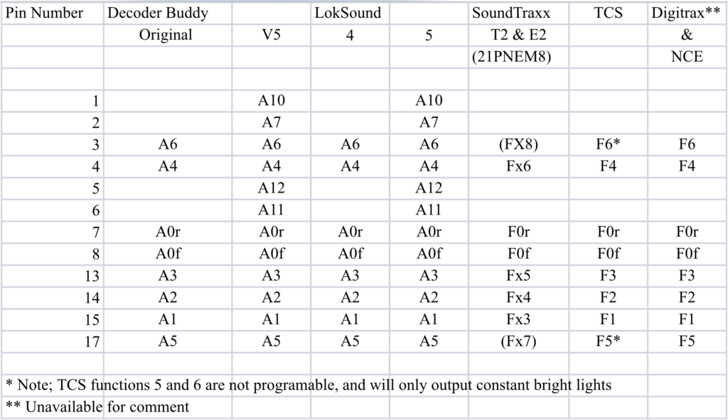
I’ve been getting a number of questions about the nomenclature on the pads of the small connector board. It is a little confusing at first. Here is a table that should straighten out the pad labels.
The first column has the pinouts from the 21-pin connector. The second column has the pad labels on the original Decoder Buddy’s small connector board. The third column has the pad labels on the V5 Decoder Buddy’s small connector board. The rest of the columns are the output labels of the different manufacturers 21-pin decoders. This chart should clear up any questions or confusion. If not, feel free to contact me
Basic Installation
- Tools Required:
- Soldering iron 15 Watt range
- Solder and flux
- Cutting pliers & pliers
- #1 Phillips screw driver
- #2 Phillips screw driver to remove the weights from the frame
- Wire stripper
- Tweezers
Checklist Procedure:
- Remove the shell of the locomotive
- De-solder or cut wires from printed circuit board
- Track wires (2 or more)
- Speaker wires (2)
- Motor wires (2)
- Light wires
- Stay alive wires (2)
- it is important to label (or measure) polarity
- Remove printed circuit board
- Attach the Decoder Buddy motherboard to the chassis, frame weights or motor.
- Solder Track wires (2 or more)
- Speaker wires (2)
- Motor wires (2), (test the direction of the motor before soldering)
- Stay alive wires (2) to the correct polarity terminals (U+ and GND) if desired
- LED light wires to the connector board
- Attach the connector board to the motherboard
- Test the installation before firmly attaching the shell
Enjoy your newly updated locomotive!!!
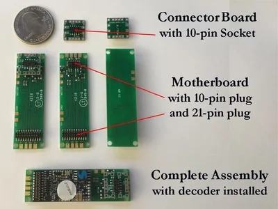
Additional V1 Motherboard Information
The mother board and the connector board are easier to see in this expanded view (above).
On the motherboard the four pads arranged vertically on each end are, from top to bottom, Track, Speaker, Speaker, Track. The Speaker pads are wired in parallel, top to top and bottom to bottom. The four labeled pads across the top are U+ {a nominal 14 volts and the place where the stay alive blue (+) wire is attached,} GND is ground for the stay alive and two MOTOR connections (Orange on the left and Gray on the right). The two motor pads have through holes in the center to allow for wire insertion from the bottom of the printed circuit board for a neater connection. A consistent motor connection color scheme does not seem to exist so these two pads are not labeled as to polarity or color. You should test that the locomotive runs in the correct direction before reinstalling the shell. U+ and GND are provided for a stay alive. The NMRA Standards state that the positive pin (U+) of the 21 pin decoder should be connected to the blue wire (+) of the capacitor (stay alive). The 21 pin connectors should fit into the decoder easily. Do not try to force either connector board or decoder onto the pinned headers on the motherboard until pins are correctly positioned. After the pins are aligned properly firmly press the connector board or the decoder onto the motherboard so there is no space between the header and the printed circuit board. If disassembly is required a sharp or narrow object inserted at the end of the connector to move the board a little at a time from each end is effective.
Additional V1 Connector Board Information
The connector board is arranged so the wires from one end of the locomotive are routed though one side of the locomotive and wires from the opposite end are routed through the other side. Function 0f is usually the front headlight and function 0r is usually the rear headlight. A1, A3 and A5 occupy the pads on one side of the connector board. This was done in an attempt to organize the decoder functions and output wires to the front and back of the locomotive. (See the compatibility table for different decoder manufacturer’s pin configuration outputs.) U+, the blue wire or common are all connected to the four holed pads which are both connected within the connector board. Note that when the direction of the <=DECODER points toward the 21 pin decoder the keyed 10 pin connector will mate properly. The connector board and the pinned header on the motherboard should fit together easily. Do not try to force either connector board or decoder onto the headers on the motherboard until pins correctly positioned. After the pins are aligned properly firmly press the connector board or the decoder onto the motherboard so there is no space between the header and the printed circuit board. In some installations it may be possible to separate the connector board from the motherboard before removing the locomotive shell. This makes the process of separating the frame and motor parts from the lights in the shell less cumbersome.
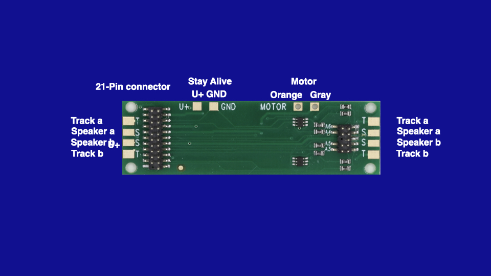
Additional V5 Motherboard Information
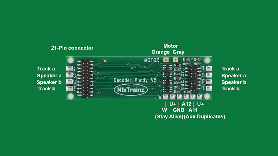
The mother board is easier to see in this expanded view (above). On the motherboard the four pads arranged vertically on each end are, from top to bottom, Track, Speaker, Speaker, Track. The Speaker pads are wired in parallel, top to top and bottom to bottom. The two labeled pads across the top are the two MOTOR connections (Orange on the left and Gray on the right). The two motor pads have through holes in the center to allow for wire insertion from the bottom of the printed circuit board for a neater connection. A consistent motor connection color scheme does not seem to exist so these two pads are not labeled as to polarity or color. You should test that the locomotive runs in the correct direction before reinstalling the shell. The five labeled pads across the bottom are U+ {a nominal 14 volts and the place where the stay alive blue (+) wire is attached,} GND is ground for the stay alive. U+ and GND are provided for a stay alive. The NMRA Standards state that the positive pin (U+) of the 21 pin decoder should be connected to the blue wire (+) of the capacitor (stay alive). The 21 pin connectors should fit into the decoder easily. Do not try to force either connector board or decoder onto the pinned headers on the motherboard until pins are correctly positioned. After the pins are aligned properly firmly press the connector board or the decoder onto the motherboard so the pins of the 21 pin connector are flush with the top of the plastic connector on the top of the decoder. If disassembly is required a sharp or narrow object inserted at the end of the connector to move the board a little at a time from each end is effective.
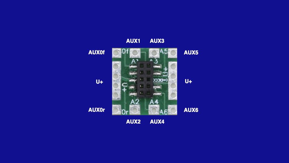
Additional V5 Connector Board Information
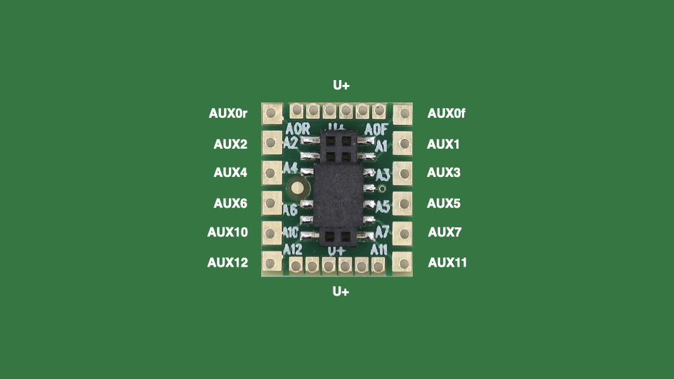
The connector board is arranged so the wires from one end of the locomotive are routed though one side of the locomotive and wires from the opposite end are routed through the other side. Function A0f is usually the front headlight and function A0r is usually the rear headlight. A1, A3, A5, A7 and A11 occupy the pads on one side of the connector board. This was done in an attempt to organize the decoder functions and output wires to the front and back of the locomotive. (See the compatibility table for different decoder manufacturer’s pin configuration outputs.) U+, the blue wire (may be the red wire on the LED) are all common are all connected to the six small pads on each end. These are all connected within the connector board. Note that when the direction of the large gold dot is on the side toward the 21 pin decoder the keyed 14 pin connector will mate properly. The connector board and the pinned header on the motherboard should fit together easily. Do not try to force either connector board or decoder onto the headers on the motherboard until pins correctly positioned. After the pins are aligned properly firmly press the connector board or the decoder onto the motherboard so there is no space between the header and the printed circuit board. In some installations it may be possible to separate the connector board from the motherboard before removing the locomotive shell. This makes the process of separating the frame and motor parts from the lights in the shell less cumbersome.
Additional Mini Motherboard Information
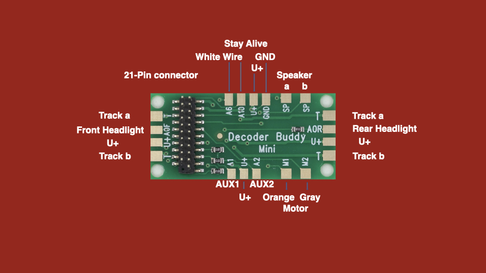
It is important to note that the A6 and A10 pads are logic voltage, 5 volts. These are provided to control a Power Pack, smoke unit, servo or whatever. They are low voltage, low current outputs. There are only four (lighting) function outputs on the motherboard.
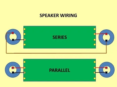
Speaker Wiring
Two or more speakerscan be wired to the Decoder Buddy.
Additional Resources
MANUFACTURERS WEBSITE: |
|
SOUND CONFIGURATION & SOUND FILE RESOURCES: |
|
FIRMWARE & SOFTWARE RESOURCES: |
|
PRODUCT MANUALS & TECHNICAL DOCUMENT RESOURCES: |
|
MANUFACTURERS WARRANTY & REPAIRS: |
|
ADDITIONAL INFORMATION - DCC TIPS: |
|
ADDITIONAL INFORMATION (1): |
|
ADDITIONAL INFORMATION (2): |
Additional Information
PRODUCT CLASS : |
All Scales |
DECODER TYPE: |
Adapter Board |
DECODER INTERFACE (PRIMARY): |
NA |
DECODER INTERFACE (SECONDARY): |
Proprietary* |
SIZE-INCH (L x W x H): |
0 x 0 x 0 in |
SIZE-METRIC (L x W x H): |
0 x 0 x 0 mm |
MOTOR CURRENT (CONTINUOUS): |
NA |
FUNCTION CURRENT (MAX): |
NA |
NORMAL OUTPUT FUNCTIONS: |
12 |
KEEP-ALIVE INTERFACE: |
NA |
KA INPUT VOLTAGE (MAX): |
NA |
KA TOTAL CAPACITANCE: |
NA |
SPEAKER INTERFACE: |
NA |
ADDITIONAL FEATURES: |
NA |
NOTES (1): |
* - NixTrainz Decoder Buddy "small connector board" Interface |
NOTES (2): |
NA |
Related Products

NixTrainz Decoder Buddy Mini 1k Ohm Resistor 21-HW - 21MTC Adapter Board - NMRA-NEM660 21MTC Integral Connector
NixTrainz

NixTrainz Decoder Buddy 8 Output Original 2.2k Ohm Resistor 21-HW - 21MTC Adapter Board - NEM660 21MTC Integral Connector
NixTrainz

NixTrainz Decoder Buddy 12 Output V5B 2.2k Ohm Resistor 21-HW - 21MTC Adapter Board - NEM660 21MTC Integral Connector
NixTrainz


ZIMO MSTAPG DCC Decoder Test and Connector Board - Large Scale
ZIMO DCC


ZIMO MSTAPK DCC Decoder Test and Connector Board - Small Scale
ZIMO DCC


ZIMO MXTAPS DCC Decoder Test and Connector Board - Small Scale
ZIMO DCC